When resistor, inductor and capacitor are connected in series across a voltage supply, the circuit so obtained is called series RLC circuit.


 NOTE: For remembering the phase relationship between voltage and current, learn this simple word called 'CIVIL', i.e in capacitor current leads voltage and voltage leads current in inductor.
 RLC Circuit
For drawing the phasor diagram of series RLC circuit, follow these steps:
RLC Circuit
For drawing the phasor diagram of series RLC circuit, follow these steps:
Phasor Diagram of Series RLC Circuit
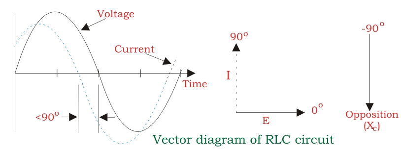
The phasor diagram of series RLC circuit is drawn by combining the phasor diagram of resistor, inductor and capacitor. Before doing so, one should understand the relationship between voltage and current in case of resistor, capacitor and inductor.
- Resistor In case of resistor, the voltage and the current are in same phase or we can say that the phase angle difference between voltage and current is zero.
- Inductor In inductor, the voltage and the current are not in phase. The voltage leads that of current by 90° or in the other words, voltage attains its maximum and zero value 90° before the current attains it.
- Capacitor In case of capacitor, the current leads the voltage by 90° or in the other words, voltage attains its maximum and zero value 0° after the current attains it i.e the phasor diagram of capacitor is exactly opposite of inductor.
NOTE: For remembering the phase relationship between voltage and current, learn this simple word called 'CIVIL', i.e in capacitor current leads voltage and voltage leads current in inductor.RLC Circuit
For drawing the phasor diagram of series RLC circuit, follow these steps:
0 comments:
Post a Comment